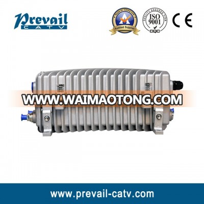
1. Product Summary
WR-1002MLD-GD outdoor optical node can be equipped 1 forward path optical receiver module, 1 return path optical transmitter module, 1 Ethernet transponder module and 1 switching power supply module. Advanced AGC technology and its equalizer and attenuator are built by fixed attenuator . Adopts voltage monitoring to the key points and optical power indicator display. Forward path two-way output level is up to 112dBμV at most.
2. Performance Characteristics
n The forward path optical receiving part adopts advanced optical AGC technology, the input optical power range extended to -8~+2dBm.
n Forward path optical receiving part: RF operating bandwidth extended to 1GHz, each way maximum output level is up to 112dBμV.
n Both equalizer and attenuator are built by fixed attenuator in order to manage accessories expediently.
n The RF amplification part adopts pluggable modular design, which can be replaced more quickly without disassembling RF cable connectors.
n Built-in perfect condition monitoring circuit and support Ethernet transponder, remotely management by the NMS.
n Built-in tri-state gate switch circuit in the return path. Three states passthrough, -6dB and OFF can be remotely set by the network management transponder.
3. Technique Parameter
3.1 Link testing conditions
The performance parameters of this manual according to the measuring method of GY/T 194-2003 < Specifications and methods of measurement on optical node used in CATV systems >, and tested in the following conditions.
1. Forward optical receive part: with 10km standard optical fiber, passive optical attenuator and standard optical transmitter composed the testing link. Set 59 PAL-D analog TV channel signal at range of 45/87MHz~550MHz under the specified link loss. Transmit digital modulation signal at range of 550MHz~862/1003MHz, the digital modulation signal level (in 8 MHz bandwidth) is 10dB lower than analog signal carrier level. When the input optical power of optical receiver is -1dBm, the RF output level is two-way splitter output 106dBμV, with 8dB output slope, measure the C/CTB, C/CSO and C/N.
2. Return optical transmit part: Link flatness and NPR dynamic range are the link indexes which is composed of return path optical transmitter and optical receiver.
Note: When the rated output level is the system full configuration and the receiving optical power is -1dBm, equipment meets the maximum output level of link index. When the system configuration degrade (that is, the actual transmission channels reduce), the output level of equipment will be increased.
Friendly Notice: Suggest you setting the RF signal to 6~9dB slope output in the practical engineering application to improve the nonlinear index (behind the node)of the cable system.
3.2 Performance Parameters
Item Unit Technical Parameters
Forward Optical Receive Part
Optical Parameters
Optical AGC control range dBm -8~+2(Default value: -7)
Optical Return Loss dB >45
Optical Receiving Wavelength nm 1100 ~ 1600
Optical Connector Type — FC/APC,SC/APC or specified by the user
Optical Fiber Type — Single mode
Link Performance
C/N dB ≥ 51 @-1dBm optical input,
output level is 108dBμV, EQ 8dB
C/CTB dB ≥ 65
C/CSO dB ≥ 60
RF Parameters
Frequency Range MHz 45/85 ~862/1003
Flatness in Band dB ±0.75
Rated Output Level dBμV ≥ 108
Max. Output Level dBμV ≥ 112
(Optical AGC controlling range : +2~-7)
Output Return Loss dB (85 ~550MHz)≥16 / (550~1000MHz) ≥14
Redundant Receiver Isolation dB ≥75
Output Impedance Ω 75
Reverse Optical Transmit Part
Optical Parameters
Optical Transmit Wavelength nm 1310±10,1550±10 or specified by the user
Laser Type — DFB or FP Laser
Output Optical Power mW 1-2
Optical Connector Type — FC/APC,SC/APCor specified by the user
RF Parameters
Frequency Range MHz 5 ~ 65(or specified by the user)
Flatness in Band dB ±0.75
Input Level dBμV 75~ 85
Input Retrun Loss dB ≥16
Independent Transmitter Isolation dB ≥60
Input Impedance Ω 75
NPRDynamic Range dB ≥15(NPR≥30 dB)
Using DFB Laser ≥10(NPR≥30 dB)
Using FP Laser
General Performance
Power Voltage V A:AC(150~265)V;B:AC(35~90)V
Feed current through A 10
Operating emperature ℃ -40~+60
Storage temperature ℃ -40~+70
Relative humidity % Max. 95% no condensation
Consumption VA ≤ 42
Dimension mm 350(L)×240(W)×135(H)